BIAS subsystem
The BIAS unit is a subsystem within the Solar Orbiter’s RPW instrument. The BIAS unit (1) drives bias currents to the three RPW antennas/probes (DC, -60 to +60 μA) and (2) amplifies and distributes analog voltage signals from before-mentioned antennas in the LF frequency range (0 to 10 kHz). Selected analog output signals are then passed on from the BIAS unit to receivers LFR (nominal) and TDS (redundant).
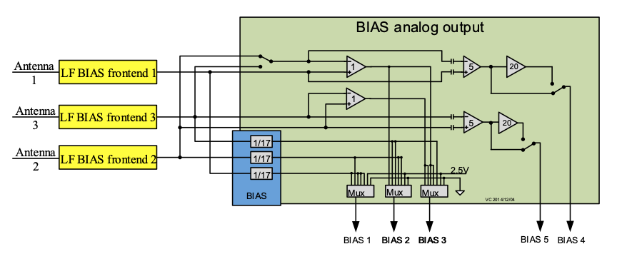
Signals are either (1) single-probe measurements which can be used for e.g. deriving density and s/c potential estimates, or (2) differential-probe measurements (voltage difference between probes) for deriving e.g. electric field estimates.
In all, the BIAS unit can produce nine different types of analog signals of which a subset are passed on to LFR or TDS and are later downlinked to ground, see below table. At most three of these nine signals are simultaneously downlinked at any given time, depending on BIAS multiplexer settings, BIAS relay settings, and LFR/TDS settings.
| BIAS unit input/output | Group of signals | Signals and relationship to other signals | Comments |
|---|---|---|---|
| Input | Antenna signal 1-3 after LF preamplifier | V1_LF V2_LF V3_LF |
Signal is not downlinked |
| Output | DC single probe channels | V1_DC = V1_LF × α V2_DC = V2_LF × α V3_DC = V3_LF × α |
Amplified by α=1/17 |
| DC differential channels | V12_DC = (V1_LF -V2_LF) × β V13_DC = (V1_LF-V3_LF) × β V23_DC = (V2_LF-V3_LF) × β |
No amplification (β=1) | |
| AC differential channels | V12_AC = (V1_LF – V2_LF) × γ V13_AC = (V1_LF – V3_LF) × γ V23_AC = (V2_LF – V3_LF) × γ |
Amplified by either γ=5 or γ=100. High-pass filtered from 50 Hz. Higher accuracy but reduced range compared to “DC differential signals”. |