Time Domaine Sampler (TDS)
TDS receiver’s overview
The Time Domain Sampler (TDS), a medium frequency receiver dedicated to waveform measurements. TDS is designed to capture electromagnetic waveform snapshots in the frequency range from 200 Hz to 200 kHz, resolving plasma waves near the electron plasma frequency and in the range between the proton and electron plasma frequencies, as well as transient signals in antenna voltage, associated with interplanetary dust impacts.
TDS samples three analog signals from the high frequency preamplifiers of RPW antennas (V1, V2 and V3) and one signal from the high frequency winding of the SCM search coil (BMF) as schematically seen in Figure 1. The analog front end of TDS implements a bandpass filter between approximately 200 Hz and 350 kHz, and a configurable gain switch allowing to increase the analog gain by 12 dB comparing to the baseline low gain setting option. This gain is configured by a telecommand and can be set independently for each channel. Before digitization, the analog signals are routed through a multiplexer bank which select the signals to be digitized by each of the four analog to digital converters (ADC). For electric field measurements, the multiplexers can be used to choose between monopole antenna measurements, where the antenna voltage relative to the spacecraft potential is measured, or dipole measurements, where differential voltages between RPW antennas are sampled instead.
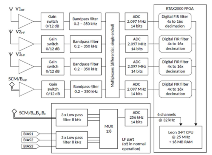
The high frequency analog signals are digitized by four 14-bit ADCs at a sampling frequency of 2097.1 kHz. This oversampled digital signal is afterwards decimated by a configurable factor of 4, 8, 16 or 32 after being processed by anti-aliasing FIR filters. The decimating filters are implemented in FPGA logic, but the filter coefficients are uploaded to the FPGA by the flight software and multiple sets with slightly different characteristics can be chosen by a telecommand. This decimated waveform is then used as the input digital signal for waveform snapshots and TDS statistical products. This configurable decimation allows the TDS sampling rate to be set to one of the four values: 524.275 ksps, 262.138 ksps, 131.069 ksps or 65.534 ksps.
A large number of input configurations is allowed by the TDS input multiplexers, but only three multiplexer settings listed in Table 1. are used routinely in scientific operations. This list includes the monopole configuration SE1 suitable for dust impact measurements, but the measurements contain more noise and spurious signals of spacecraft origin. The measurements in the DIFF1 dipole configuration are cleaner, but since the three RPW antennas lie in the same plane and essentially only allow to measure a projection of the electric field to the antenna plane, the three dipole measurements in the same plane are redundant and this configuration does not easily allow to study variations in antenna to spacecraft voltage required for dust impact measurements. The best compromise is offered by the XLD1 which combines two electric field dipoles in two channels and one monopole in the third channel.
| Channel CH1 | Channel CH2 | Channel CH3 | Channel CH4 | |
| SE1 | V1 | V2 | V3 | BMF |
| DIFF1 | V1 – V3 | V2 – V1 | V3 – V2 | BMF |
| XLD1 | V1 – V3 | V2 – V1 | V2 | BMF |
TDS supports all the operational modes of RPW. Survey NORMAL and BURST modes are implemented in the same way in TDS, but BURST mode has a separate configuration that can be applied when RPW switches to BURST mode. This typically includes higher rate products, such as the maximum amplitude (MAMP). In the selective burst modes SBM1, which shall be used during interplanetary shock crossings, and SBM2, to be used for in-situ type III regions, TDS generates all the normal mode products but can generate additional periodic (in SBM1) or triggered (in SBM2) snapshots.
On-board detection
The TDS flight software implements on-board processing and detection of the captured snapshots which allows the instrument to classify the observations into three categories: waves, dust impacts and other signals. This algorithm described here is used to select the most relevant waveform snapshots for transmission to the ground by assigning a quality factor and provides statistical characterization of processed snapshots. This algorithm efficiently distinguishes between coherent waves, such as Langmuir waves, characterized by a narrow bandwidth and small peak to median ratio, and isolated voltage spikes associated with impacts of interplanetary dust, which result in a very large peak to median ratio and wide bandwidth. In its nominal scientific operation (NORMAL, BURST or SBM1/SBM2 modes), the TDS acquires one waveform snapshot every second. Each snapshot is then processed in the following steps:
- TDS calculates a maximum of the absolute value of all samples in the snapshot Vmax, an RMS value Vrms and a median absolute value Vmed. This calculation, as well as all the subsequent steps, are only performed on one TDS channel selected by a telecommand.
- If Vmax is less than a configured minimum amplitude threshold, the snapshot is discarded as insignificant and no further processing is done.
- A Fourier spectrum is calculated from the snapshot using the standard Welch method, by dividing the snapshot into blocks of 2048 points, applying a Hann window and a discrete Fourier transform (FFT) to each block and averaging all the FFT power spectra. Afterwards, the algorithm finds the largest peak in the spectrum (corresponding to the estimated wave frequency fwave) and calculates its bandwidth BW at half of the peak amplitude.
- A decision on event classification is made based on following conditions: if Vmax /Vmed > T1dust and BW > T2dust the event is classified as a dust impact. Otherwise, if Vmax /Vmed ≤ T1wave and BW ≤ T2wave the event is a wave. Here, T1dust,wave and T2dust,wave are fixed thresholds configurable by telecommands. The criterion reflects the fact that wave observations are typically narrowband and the peak value in the snapshot is not much larger than the median value, while the opposite holds for sharp transients such as the dust impacts.
- In the final step, the statistical values computed by TDS are updated. The wave, resp. dust, counter is incremented if a wave, resp. dust, event is identified. Maximum and RMS values of snapshot amplitudes are updated based on the processed snapshot. For waves, a special processing step is added, where wave specific properties (frequency, peak and RMS amplitude) are added to a special statistic restricted to wave events. These values are used to update the values for the STAT packet defined below and the on-board collected histograms. In this step we also assign a quality factor to the current snapshot, defined nominally as Q = Vmax /BW. TDS can also use different quality factors, such as the amplitude alone.